Connecting Multiple On-Premises Branch Networks Through a VPN Hub
In this solution we are going to demonstrate how an Enterprise A can implement communication between its two on-premises data centers in order to meet service requirements.
Solution Design
Figure 1 shows the networking where the VPN service is used to connect the two on-premises data centers.
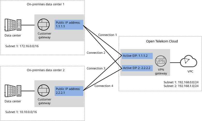
Figure 1: Networking diagram
Advantages
- A VPN gateway on the cloud can function as a VPN hub to enable communication between on-premises branch sites. This eliminates the need to configure VPN connections between every two sites.
- A VPN gateway provides two IP addresses to establish dual independent VPN connections with each customer gateway. If one VPN connection fails, traffic can be quickly switched to the other VPN connection, ensuring reliability.
Limitations and Constraints
- The local and customer subnets of the VPN gateway cannot be the same. That is, the VPC subnet and the data center subnet to be interconnected cannot be the same.
- The IKE policy, IPsec policy, and PSK of the VPN gateway must be the same as those of the customer gateway.
- The local and remote interface address configurations on the VPN gateway and customer gateway are reversed.
- The security groups associated with ECSs in the VPC permit access from and to the on-premises data center.
Planning Networks and Resources
Data Plan
| Category | Item | Data |
|---|---|---|
| VPC | Subnet that needs to access the on-premises data centers | • |
| VPN gateway | Interconnection subnet | This subnet is used for communication between the VPN gateway and VPC. Ensure that the selected interconnection subnet has four or more assignable IP addresses. |
| HA Mode | Active-active | |
| EIP | EIPs are automatically generated when you create them. By default, a VPN gateway uses two EIPs. In this example, the EIPs are as follows: | |
| VPN connection | Tunnel interface address | This address is used by a VPN gateway to establish an IPsec tunnel with a customer gateway. At the two ends of the IPsec tunnel, the configured local and remote tunnel interface addresses must be reversed. |
| On-premises data center 1 | Subnet that needs to access the VPC | 172.16.0.0/16 |
| Customer gateway in on-premises data center 1 | Public IP address | This public IP address is assigned by a carrier. In this example, the public IP address is: |
| Tunnel interface address | • VPN connection 1: | |
| On-premises data center 2 | Subnet that needs to access the VPC | 10.10.0.0/16 |
| Customer gateway in on-premises data center 2 | Public IP address | This public IP address is assigned by a carrier. In this example, the public IP address is: |
| Tunnel interface address | • VPN connection 3: | |
| IKE and IPsec policies | PSK | Test@123 |
| IKE policy | • Authentication algorithm: | |
| IPsec policy | • Authentication algorithm: |
Table 1: Data Plan
Prerequisites
- Cloud side
- A VPC has been created. For details about how to create a VPC, see Creating a VPC.
- Security group rules have been configured for the VPC, and ECSs can communicate with other devices on the cloud. For details about how to configure security group rules, see Security Group Rules.
- Data center side
- IPsec has been configured on the VPN devices in the two on-premises data centers. For details, see Administrator Guide.
- The remote subnets of the VPN device in on-premises data center 1 must contain the local subnet of the T Cloud Public VPC and the subnet to be interconnected in on-premises data center 2. The remote subnets of the VPN device in on-premises data center 2 must contain the local subnet of the T Cloud Public VPC and the subnet to be interconnected in on-premises data center 1.
Configuration
T Cloud Public VPNs support static routing mode, BGP routing mode, and policy-based mode. The following uses the static routing mode as an example.
-
Configure a VPN gateway.
-
Choose Virtual Private Network -> Enterprise – VPN Gateways, and click Create VPN Gateway.
-
Set parameters as prompted.
Table 1 only describes the key parameters for creating a VPN gateway.
Table 1 Description of VPN gateway parameters
Parameter Description Value Name Name of a VPN gateway. vpngw-001 Network Type Select Public network. Public network Associate With Select VPC. If the VPN gateway is associated with an enterprise router, select Enterprise Router. VPC VPC T Cloud Public VPC that the on-premises data centers need to access. vpc-001(192.168.0.0/16) Local Subnet VPC subnets that the on-premises data centers need to access. 192.168.0.0/24,192.168.1.0/24 Interconnection Subnet This subnet is used for communication between the VPN gateway and VPC. Ensure that the selected interconnection subnet has four or more assignable IP addresses. 192.168.2.0/24 BGP ASN BGP AS number. 64512 HA Mode Select Active-active. Active-active Active EIP EIP 1 used by the VPN gateway to access the on-premises data center. 1.1.1.2 Active EIP 2 EIP 2 used by the VPN gateway to access the on-premises data center. 2.2.2.2
-
-
Configure customer gateways.
-
Choose Virtual Private Network -> Enterprise – Customer Gateways, and click Create Customer Gateway.
-
Set parameters as prompted.
Table 2 only describes the key parameters for creating a customer gateway.
Table 2 Description of customer gateway parameters
Parameter Description Value Name Name of a customer gateway. cgw-fw1 Routing Mode Select Static. Static Gateway IP Address IP address used by the customer gateway in on-premises data center 1 to communicate with the T Cloud Public VPN gateway.
Ensure that UDP port 4500 is permitted on the customer gateway device in the on-premises data center.1.1.1.1 -
Repeat the preceding operations to configure the customer gateway (2.2.2.1) in on-premises data center 2.
-
-
Configure VPN connections between the cloud side and on-premises data center 1.
-
Choose Virtual Private Network -> Enterprise – VPN Connections, and click Create VPN Connection.
-
Set parameters for VPN connection 1 and click Submit.
Table 3 only describes the key parameters for creating a VPN connection.
Table 3 Description of VPN connection parameters
Parameter Description Value Name Name of a VPN connection. vpn-001 VPN Gateway VPN gateway for which the VPN connection is created. vpngw-001 Gateway IP Address Active EIP bound to the VPN gateway. 1.1.1.2 VPN Type Select Static routing. Static routing Customer Gateway Name of a customer gateway. cgw-fw1 Customer Subnet Subnet in on-premises data center 1 that needs to access the VPC on T Cloud Public. A customer subnet cannot be included in any local subnet or any subnet of the VPC to which the VPN gateway is attached. Reserved VPC CIDR blocks such as 100.64.0.0/10 and 214.0.0.0/8 cannot be used as customer subnets. 172.16.0.0/16 Interface IP Address Assignment Manually specify In this example, select Manually specify. Automatically assign Manually specify Local Tunnel Interface Address Tunnel interface IP address configured on the VPN gateway. 169.254.70.1 Customer Tunnel Interface Address Tunnel interface IP address configured on the customer gateway device. 169.254.70.2 Link Detection Whether to enable route reachability detection in multi-link scenarios. When NQA is enabled, ICMP packets are sent for detection and your device needs to respond to these ICMP packets. NQA enabled PSK, Confirm PSK The value must be the same as the PSK configured on the customer gateway device. Test@123 Policy Settings The policy settings must be the same as those on the customer gateway device. Default -
Create VPN connection 2.
noteFor VPN connection 2, you are advised to use the same parameter settings as VPN connection 1, except the parameters listed in the following table.
Table 4 Parameter settings for VPN connection 2
Parameter Description Value Name Name of a VPN connection. vpn-002 Gateway IP Address Active EIP 2 bound to the VPN gateway. 2.2.2.2 Local Tunnel Interface Address Tunnel IP address of the VPN gateway. 169.254.71.1 Customer Tunnel Interface Address Tunnel IP address of the customer gateway. 169.254.71.2
-
-
Configure VPN connections between the cloud side and on-premises data center 2.
-
Choose Virtual Private Network -> Enterprise – VPN Connections, and click Create VPN Connection.
-
Set parameters for VPN connection 1 as prompted and click Submit.
Table 5 only describes the key parameters for creating a VPN connection.
Table 5 Description of VPN connection parameters
Parameter Description Value Name Name of a VPN connection. vpn-003 VPN Gateway VPN gateway for which the VPN connection is created. vpngw-001 Gateway IP Address Active EIP bound to the VPN gateway. 1.1.1.2 Customer Gateway Name of a customer gateway. cgw-fw2 VPN Type Select Static routing. Static routing Customer Subnet Subnet in on-premises data center 2 that needs to access the VPC on T Cloud Public. A customer subnet cannot be included in any local subnet or any subnet of the VPC to which the VPN gateway is attached. Reserved VPC CIDR blocks such as 100.64.0.0/10 and 214.0.0.0/8 cannot be used as customer subnets. 10.10.0.0/16 Interface IP Address Assignment Manually specify In this example, select Manually specify. Automatically assign Manually specify Local Tunnel Interface Address Tunnel interface IP address configured on the VPN gateway. 169.254.72.1 Customer Tunnel Interface Address Tunnel interface IP address configured on the customer gateway device. 169.254.72.2 Link Detection Whether to enable route reachability detection in multi-link scenarios. When NQA is enabled, ICMP packets are sent for detection and your device needs to respond to these ICMP packets. NQA enabled PSK, Confirm PSK The value must be the same as the PSK configured on the customer gateway device in on-premises data center 2. Test@123 Policy Settings The policy settings must be the same as those configured on the customer gateway device in on-premises data center 2. Default -
Create VPN connection 2.
noteFor VPN connection 2, you are advised to use the same parameter settings as VPN connection 1, except the parameters listed in the following table.
Table 6 Parameter settings for VPN connection 2
Parameter Description Value Name Name of a VPN connection. vpn-004 Gateway IP Address Active EIP 2 bound to the VPN gateway. 2.2.2.2 Local Tunnel Interface Address Tunnel IP address of the VPN gateway. 169.254.73.1 Customer Tunnel Interface Address Tunnel IP address of the customer gateway in on-premises data center 2. 169.254.73.2
-
-
Configure customer gateway devices in on-premises data centers 1 and 2.
The configuration procedures may vary according to the type of the customer gateway device. For details, see Administrator Guide.
Verification
-
About 5 minutes later, check states of the VPN connections.
Choose Virtual Private Network -> Enterprise – VPN Connections. The states of the four VPN connections are all Normal.
-
Verify that servers in on-premises data center 1 and servers in on-premises data center 2 can ping each other.